
4-20 mA and Modbus: How Fixed Gas Detectors Talk to Your Plant
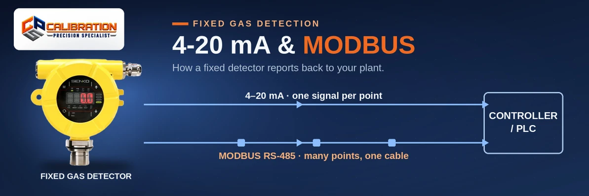
A fixed gas detector talks to your plant in one of three ways: a 4-20 mA analog loop, where 4 mA means zero gas and 20 mA means full scale; an RS-485 Modbus link, which carries the reading digitally together with alarm and fault status; or relay contacts, which carry no reading at all — just action at a setpoint. The SENKO SI-200E (from $950) offers both 4-20 mA and RS-485 Modbus on a single head, and OTIS's OI-7432 controller ($1,930) polls up to 32 detector heads over one Modbus daisy chain.
Our explainer on how a fixed gas detection system works follows the whole chain from sensor to response. This post zooms into the middle link — the signal — because it is the decision that locks in your wiring, your controller, and what your PLC can ever know about a leak.
4-20 mA: The Loop That Never Retired
The 4-20 mA current loop is the plant world's oldest surviving data format, and gas detectors still default to it for good reasons. The detector drives a current around a pair of wires, and the current is the reading, scaled linearly across the detector's range:
- 4 mA = zero — the bottom of the detector's range (0 ppm, 0% LEL, or the low end of an oxygen scale).
- 20 mA = full scale — the top of the range the detector was configured for.
- Everything between is proportional. On a 0–100 ppm carbon monoxide head, 12 mA is 50 ppm. The general math is (mA − 4) ÷ 16 × full scale.
Three properties keep the loop alive. First, the live zero: because "no gas" is 4 mA and not 0 mA, a loop sitting at 0 mA is unambiguously broken — cut wire, dead device, lost power — instead of masquerading as clean air. Second, current doesn't fade: the same current flows at every point in a series loop, so long cable runs and electrical noise that would corrupt a voltage signal leave the reading intact. Third, everything reads it: PLC analog cards, DCS inputs, chart recorders, and every gas controller on our shelf — including OTIS's OI-7480-12 ($3,365), a 12-channel controller built specifically to gather 4-20 mA transmitters of any brand under one alarm roof.
The loop's price is equally clear: one loop carries exactly one value from exactly one point. Thirty-two heads on 4-20 mA is thirty-two home-run cable pairs.
2-Wire vs. 3-Wire: Where Does the Detector's Power Come From?
- 2-wire (loop-powered) transmitters steal their operating power from the signal loop itself — the same pair of wires carries power in and the reading out. OTIS's OI-6750-XP ($1,380) is the clean example: an explosion-proof head in 24 gas/range combinations that drops onto existing 2-wire infrastructure, which is why loop-powered heads are the retrofit favorite. RKI's T2A (from $1,826, 39 factory configurations across 18 gases) is the same architecture from RKI.
- 3-wire transmitters take power on a separate wire and return the 4-20 mA signal on another, freeing the device from the loop's tiny power budget — headroom that local displays, relays, and hungrier sensors can need. RKI's T3A (from $1,650, 37 configurations across 21 gases) is the 3-wire counterpart to the T2A, and the two sit side by side in the catalog precisely because plants are wired both ways.
Neither is "better." The right one is the one your existing cable plant and controller inputs already speak — which is why the same gas, in the same housing family, is sold in both.
How Does the Plant Know a Detector Has Failed?
A signal format earns trust by how it behaves on a bad day. On 4-20 mA, failure vocabulary is standardized by the NAMUR NE43 convention, which most modern transmitters follow:
| Loop current | Meaning under NAMUR NE43 |
|---|---|
| 3.8–20.5 mA | Valid measurement (the ends of the band are saturation, slightly under/over range) |
| ≤3.6 mA | Transmitter fault (downscale failure signal) |
| ≥21 mA | Transmitter fault (upscale failure signal) |
| 0 mA | No signal at all — open loop, dead device, or lost loop power |
Two honest caveats. First, NE43 is a convention, not a law of physics: the exact fault current a given head drives is whatever its manufacturer implemented, so the device manual is the authority for the heads you own. Second, an analog loop can only say "fault" — it cannot say why. Devices add their own channels for that: the SENKO SI-H100 carries a dedicated fault relay alongside its 4-20 mA output (plus a 4 mA / 20 mA output-calibration step in its menu, so the loop reads true at the PLC), and the OI-7480-12 controller provides a dedicated fault terminal. When the "why" matters continuously, that's the argument for going digital.
Modbus over RS-485: The Reading, Plus Everything Else
Modbus RTU over RS-485 replaces the per-point loop with a shared digital bus. Each head gets an address; the controller polls addresses in turn and reads registers — memory locations that hold not just the gas value but its units, alarm state, and fault diagnostics. What that buys:
- Many points, one cable. OTIS's OI-7432 ($1,930) polls up to 32 OI-6000-series heads on a single daisy chain — against thirty-two home-run loops for the same points on 4-20 mA.
- Status, not just value. A Modbus head reports "in alarm," "in fault," and "sensor end-of-life" as data, where a loop can only infer trouble from an out-of-band current.
- Manufacturers publish the map. SENKO publishes the full Modbus address map for the SI-H100 in its manual, so an integrator can pull any register the device exposes; the SI-200E likewise pairs its 4-20 mA output with RS-485 Modbus (and offers HART as an option — digital data overlaid on the analog loop, for plants built that way).
The costs are configuration and shared fate: every device needs a unique address and matching communication settings before anything works, and a wiring fault on a shared bus can take a segment of heads dark together, where a cut loop wire only ever kills its own point.
Relays: The Signal That Isn't a Signal
A relay output carries one bit of information — the contact is open, or it is closed — and that bit is action, not data: at the setpoint, the contact switches the horn, the strobe, the fan starter, or the PLC input wired to it. Relays are how detection becomes response without any other system being awake, configured, or even present. Controllers pair them with the data signals rather than competing with them: the OI-7432 carries four dry-contact alarm relays (4-amp fused, latching or non-latching) alongside its Modbus, and RKI's Beacon 110 single-point controller's relays are rated 10 amps — enough to drive external horns and alarms directly. Specify relays for what must happen locally and immediately; specify a data signal for what must be known, trended, and proven later.
4-20 mA vs. Modbus vs. Relays: Side by Side
| 4-20 mA loop | RS-485 Modbus | Relay contacts | |
|---|---|---|---|
| Carries | One value per point | Value + units + alarm/fault status per point | One bit: actuated or not |
| Wiring | One pair per point, home-run | One daisy-chained bus for many points | Per function, to the device being switched |
| Devices per run | 1 | Up to 32 heads on the OI-7432's chain | 1 contact set per action |
| Failure signaling | Out-of-band current (NE43: ≤3.6 or ≥21 mA); 0 mA = dead loop | Fault reported as data, with device status | A fault relay can be wired fail-safe |
| Configuration | Scale the input to the detector's range | Address and register map per device | Setpoint and latch behavior |
| Best at | Retrofits, PLC/DCS analog inputs, one-signal simplicity | New multi-point systems, diagnostics, trending | Local action that must not depend on any network |
Which Signal Should You Specify?
- Retrofitting onto existing loops or analog PLC cards: 4-20 mA, and 2-wire loop-powered heads (OI-6750-XP, RKI T2A) that reuse the cable already in the tray.
- Building a new multi-point system: Modbus heads on a daisy chain into a controller like the OI-7432 — one cable plant, full status data, and the controller still hands Modbus and relays upstream to the plant.
- One point that must act on its own: a head or stand-alone monitor with its own relays (SI-200E, SI-H100) — no controller required for the point to alarm and respond.
- Mixed plants, which is most plants: heads that speak both. The SI-200E outputs 4-20 mA and Modbus simultaneously, so the loop can feed today's PLC card and the bus can feed tomorrow's — our SENKO fixed comparison covers that range head by head, and the whole fixed systems category is organized around these choices.
The Bottom Line
4-20 mA is one honest number per point, with a live zero that exposes a dead loop and fault currents standardized under NAMUR NE43. Modbus is the whole conversation — value, status, and faults for up to 32 heads on one daisy-chained cable — at the price of configuration. Relays are neither: they are the muscle that acts at a setpoint whether or not any data system is listening. Mature systems use all three, each where it is strongest.
Specifying signals for a new system, or trying to make new heads talk to an existing plant? Call us at 865-900-8844 with the controller or PLC you already own and the points you need to add — the signal decision usually makes itself from there — or reach us through Contact Us.
Frequently Asked Questions
What does 4 mA mean on a gas detector output? Zero — the bottom of the detector's configured range. A 4-20 mA gas detector outputs 4 mA when it reads no gas (0 ppm, 0% LEL, or the low end of its scale), rising linearly to 20 mA at full scale. The 4 mA "live zero" is deliberate: it lets the receiving system distinguish a true zero reading from a dead loop, because a broken wire or failed device drops the loop to 0 mA — a value that can never be mistaken for clean air.
What does 12 mA mean on a 0–100 ppm gas detector? 50 ppm. A 4-20 mA output is linear, and 12 mA is exactly halfway between 4 and 20 mA, so it represents halfway up the detector's range: (12 − 4) ÷ 16 × 100 ppm = 50 ppm. The same formula works for any range — on a 0–25% oxygen transmitter, 12 mA is 12.5% O₂. What changes between installations is the full-scale value the loop was scaled to, which is why the range belongs on the drawing and the transmitter's configuration record.
How does a PLC know when a gas detector has failed? By the loop current leaving the measurement band. Under the NAMUR NE43 convention most modern transmitters follow, 3.8–20.5 mA is a valid measurement, while a drop to ≤3.6 mA or a drive to ≥21 mA is the transmitter announcing its own fault; a flat 0 mA means the loop itself is open or unpowered. Exact fault behavior is set by each manufacturer, so confirm it in your head's manual — and note that some devices add a dedicated fault relay or fault terminal so the failure is signaled even if the loop is the thing that failed.
What is the difference between a 2-wire and a 3-wire gas transmitter? Power routing. A 2-wire transmitter is loop-powered: the same pair of wires that carries its 4-20 mA signal also powers the device, which makes it the simplest drop-in for existing loops — OTIS's OI-6750-XP ($1,380) and RKI's T2A (from $1,826) are built this way. A 3-wire transmitter, like RKI's T3A (from $1,650), takes power on a separate wire and returns the signal on another, giving the device more power headroom for displays, relays, and hungrier sensors. The signal both produce is the same 4-20 mA.
Can multiple gas detectors share one cable? On Modbus, yes — that's the architecture's point. RS-485 Modbus heads are daisy-chained on a single bus, each with its own address: OTIS's OI-7432 controller polls up to 32 OI-6000-series heads over one chain. On 4-20 mA, no — each loop is one pair of wires carrying one point's reading, so thirty-two analog points means thirty-two cable runs back to the controller or PLC. That wiring difference is usually what decides the architecture on larger systems.
How far can a 4-20 mA signal run? Much farther than a voltage signal — current loops are chosen partly because the current is the same at every point in the loop, so cable resistance and industrial electrical noise don't corrupt the reading the way they would a 0–10 V signal. There is no single honest distance figure: the limit is the loop's power budget — supply voltage minus the voltage drops of the transmitter, the receiver, and the cable run at your wire gauge. Your installer calculates it per loop; in practice, in-plant runs are rarely the constraint.
Is Modbus better than 4-20 mA for gas detectors? Better at different things. Modbus carries more — the reading plus alarm state and fault diagnostics, for many heads on one cable — but it needs addressing and configuration, and a bus wiring fault can darken a whole segment. A 4-20 mA loop carries one value with almost zero configuration, is readable by every PLC and controller ever made, and fails one point at a time. New multi-point systems usually justify Modbus; retrofits and PLC-analog plants usually justify the loop. Many heads, like the SENKO SI-200E, output both at once.
What is HART on a gas detector? HART is a digital communication signal overlaid on a standard 4-20 mA loop: the analog current keeps carrying the reading to the control system exactly as before, while a HART communicator or asset-management system can read device identity, configuration, and diagnostics over the same two wires. It is an option on some fixed heads — SENKO offers HART on the SI-200E — and it suits plants whose instrument shops already work in HART. If your plant doesn't, Modbus or plain 4-20 mA will serve you as well.
Do I need relay outputs if my detectors have Modbus? Usually yes, somewhere in the system. Modbus tells a controller or PLC what the gas is doing; relays are what physically act — sounding the horn, starting the fan, closing the valve — and they act even if the data network or the PLC is down. That's why controllers combine both: OTIS's OI-7432 pairs its Modbus polling and output with four dry-contact alarm relays, and single-point controllers like RKI's Beacon 110 lead with 10-amp relays. Data informs; relays intervene.
Which signal should a new fixed gas detection system use? Decide from what's already in the plant. If a PLC with spare analog inputs owns the alarming, 4-20 mA heads (2-wire where loops exist) are the shortest path. If you're building detection as its own system with several points, Modbus heads on a daisy chain into a controller like the OI-7432 give you status and diagnostics with a fraction of the copper. Either way, keep relays in the design for the actions that must happen locally — and when in doubt, choose heads that output both 4-20 mA and Modbus, like the SENKO SI-200E, so the decision never has to be remade.
CPS Calibrations · 109 S. Front Street, Rockwood, TN 37854 · Fixed Systems · Calibration Gas · Calibration Services · Contact Us
Recent Posts
-
Flame Detector vs. Gas Detector: What's the Difference — and Do You Need Both?
A gas detector and a flame detector guard opposite ends of the same incident: a gas detector reads l …Oct 21st 2026 -

How Do You Test a Flame Detector? Self-Tests, Test Lamps, and NFPA 72
You test a flame detector with light, not gas — there is no span gas, no zero gas, and never an open …Oct 21st 2026 -

Why Does a Flame Detector False Alarm — and Which Type Won't?
A flame detector false alarms because something that is not a fire is producing the signal it watche …Oct 21st 2026