
Ventilation Interlocks: Wiring Gas Detection to Fans, Dampers, and Alarms
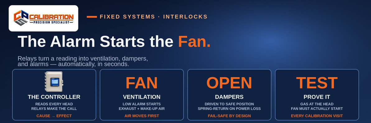
A ventilation interlock is the wired cause-and-effect chain that turns a gas alarm into action: when a fixed detector crosses its alarm setpoint, the controller's relay output starts exhaust ventilation, drives dampers to their safe position, and sounds local and remote alarms — automatically, in seconds, with no one required to be in the room. A detector that only displays a number protects no one; the interlock is what makes the reading do work.
Most fixed gas detection is sold and judged on the detector — the sensor, the range, the display. But the detector is only the first link. What happens in the sixty seconds after it alarms is decided by relays, starters, actuators, and wiring that were designed once, often years ago, and are rarely tested again. This post walks that chain in plain terms: how the signal travels, what each output actually does, what fail-safe really means, and why proving the whole chain — not just calibrating the head — is part of a real calibration visit. It builds directly on what happens on a fixed gas detection calibration visit, where the relay and ventilation test is step three of the visit.
The Chain, Link by Link
An interlocked system has four links, and each one can fail independently of the others:
- The detector measures the gas and reports to the controller — most commonly as a 4–20 mA analog signal, or over a digital bus on newer systems. It knows nothing about fans.
- The controller compares every reading against its programmed alarm setpoints and decides. This is the brain of the interlock: which alarm level does what is a controller configuration decision, covered in how to choose a gas detection controller.
- The relay output is the controller's hands. Alarm relays are dry contacts — switches. They carry control signals, not motor loads.
- The field device does the work: a motor starter that actually powers the exhaust fan, a damper actuator that drives the damper open or closed, a beacon or horn, a building-panel input that tells the wider facility an alarm exists.
That third point is the one most often misunderstood: the controller relay does not run the fan. It pilots a motor starter or contactor, and the starter carries the motor current. Wire a fan straight through a controller relay and the contact will fail — sometimes welded shut, sometimes open — and either failure hides until the day the interlock is needed. Correctly built, each output drives the device rated for the load, and the chain survives being used.
What Each Output Actually Does
A typical cause-and-effect design assigns different jobs to different alarm levels — a low alarm acts locally and early, a high alarm escalates:
- Ventilation: the first response in most occupied-space designs. The low alarm starts exhaust fans (and the make-up air path that lets them actually move air) while the leak is still small — the goal is to dilute and remove gas faster than it accumulates, not to announce a disaster already in progress.
- Dampers: motorized dampers are driven to their designed safe position — opening the exhaust path, isolating a zone, or both, depending on the room's design intent. A damper that never moves is a wall with a motor on it; its position, not its existence, is the protection.
- Alarms and notification: beacons and horns at the room's entrances (warn before entry, not just inside), plus a signal to wherever people actually are — a control room, a building automation panel, a dialer. An alarm that only sounds in the empty room it protects has done half its job.
- Shutdown interlocks: on the high alarm, some designs also shut down the process feeding the leak — closing a gas supply solenoid, stopping a compressor, de-energizing ignition sources. This is the strongest medicine and is reserved for the level where dilution alone is no longer the plan.
Where this pattern earns its keep is easy to see in rooms CPS sees constantly: a refrigeration machinery room, where detector-driven alarm and ventilation are the core of the ASHRAE 15 machinery-room requirements; a parking garage, where CO (and NO2 where diesels run) sensors start fans on demand instead of ventilating an empty structure around the clock; a battery room, where the fan is the control that keeps a slow hydrogen release from ever becoming a concentration.
Fail-Safe Is a Wiring Decision, Not a Feature
'Fail-safe' gets printed in brochures as if it were something a product has. In an interlock, it is something the wiring does — or does not do.
The principle: wire the alarm chain so that losing power or a component drives the system toward the safe state, not away from it. In practice that means alarm relays are commonly held energized in the normal, no-alarm state, so a power failure, a cut wire, or a dead controller drops the relay out into the same contact state as an alarm — fans commanded on, alarm raised. Spring-return damper actuators follow the same logic mechanically: remove power and the spring drives the damper to its safe position without asking anyone's permission.
The opposite build is depressingly common in older installs: the relay only does something when it successfully energizes, so the failure mode of the safety chain is silence — no fan, no alarm, no indication anything is wrong, because the thing that failed is the thing that was supposed to report. A controller fault output exists precisely to break that silence, and wiring it to somewhere it will be seen is part of a complete interlock, not an extra.
Latching, Delays, and Reset: The Settings That Decide Behavior
Three controller settings shape how an interlock behaves in the real world, and all three are judgment calls worth making deliberately:
- On-delay: a few seconds of delay between setpoint and output rides out the transient puff — a forklift passing the sensor, a door opening — without starting a fan for nothing. Too long a delay, and the interlock is late to a real release. The right value is short and intentional.
- Latching vs. automatic reset: a latching high alarm stays in alarm — outputs held, fan running — until a person acknowledges it, even after the reading falls. That is the right behavior where someone must investigate before the room is declared safe. Non-latching outputs reset themselves when the gas clears, which suits low-alarm ventilation: the fan runs while gas is present and stops after the air is clean, with a run-on period so it purges the last of the release instead of stopping the moment the sensor dips.
- Who can reset: a latching alarm that any passerby can silence at the panel will be silenced. Reset belongs to the people responsible for declaring the space safe.
None of these settings is visible from the detector's display. They live in the controller configuration — which is why they have to be documented, and why 'the system is wired for ventilation' is a claim that has to be proven, not remembered.
Why the Interlock Test Belongs in Every Calibration Visit
Here is the failure this post exists to prevent: a fixed system that calibrates perfectly and protects nothing. The head reads true, the certificate is clean — and the fan never starts, because a relay was bypassed during a nuisance-alarm week two years ago, a starter was replaced and the control wire never landed again, or a damper actuator seized in the position it was left in. Calibration tests the first link of the chain. Only an end-to-end test proves the rest.
That is why a proper fixed calibration visit applies gas at the head and then watches the whole design perform: the alarm level trips, the relay operates, the fan actually starts and moves air, the damper reaches its position, the notification arrives where it is supposed to. Every break in the chain is a finding on the day — quoted in writing before any repair, like everything else that surfaces on a visit. CPS designs and wires these systems as well as calibrating them; the work is covered under fixed system installation.
If you cannot remember the last time your fans answered a gas alarm, that is your answer: they are unproven. The test takes minutes inside a normal calibration visit — the expensive way to learn about an interlock is during the leak it was built for.
Frequently Asked Questions
What is a ventilation interlock in gas detection?
A ventilation interlock is the wired connection between a gas detection controller and a building's ventilation equipment: when a detector's reading crosses an alarm setpoint, the controller's relay output automatically starts exhaust fans, drives dampers to their safe position, and triggers alarms — no human action required. The detector measures; the interlock acts.
How does a gas detector start a fan automatically?
Through the controller, not directly. The detector sends its reading to the controller (usually a 4–20 mA signal); at the programmed setpoint the controller changes the state of a relay output; that relay pilots a motor starter or contactor, and the starter powers the fan. Each device in the chain handles the load it is rated for — the relay carries only the small control signal.
Can a gas detector controller run a fan motor directly?
No — controller alarm relays are dry contacts rated for control circuits, not motor current. They switch a motor starter, contactor, or actuator that is rated for the load. Wiring a fan motor through a controller relay overloads the contact; it can weld shut or fail open, and either failure stays hidden until the interlock is needed.
What does fail-safe mean for gas detection relays?
It means the wiring is arranged so a failure drives the system toward safety: alarm relays are commonly held energized while conditions are normal, so a power loss, cut wire, or controller failure drops the relay into its alarm state — fans commanded on, alarm raised — instead of failing silent. Spring-return damper actuators do the same job mechanically, driving the damper to its safe position when power is removed.
Should dampers fail open or closed on a gas alarm?
To their designed safe position — which for dampers in a gas exhaust path normally means open, so the exhaust fan can actually move air out of the room; a running fan against a closed damper ventilates nothing. The safe position is set by the room's cause-and-effect design: some designs close a damper to isolate a zone instead. What matters is that the position is deliberate, documented, and tested.
What is the difference between a latching and a non-latching gas alarm?
A latching alarm holds its outputs — fan running, beacon on — until a person manually resets it, even after the gas reading falls back to normal; it forces an investigation before the room is declared safe. A non-latching alarm resets itself when the reading clears, which suits low-alarm ventilation that should start and stop with conditions. High alarms are commonly latched; low ventilation alarms commonly are not.
Why does my exhaust fan not start when the gas detector alarms?
The detector is only the first link, so check the chain: the controller relay may not be programmed to that output, the relay may have been bypassed during past nuisance alarms, the control wire to the motor starter may be disconnected or landed wrong after a starter replacement, or the starter or fan itself may have failed. A detector can calibrate perfectly while any of these breaks sits downstream — finding which link is broken takes an end-to-end test with gas at the head.
Do parking garages need CO sensors wired to the fans?
Demand-controlled ventilation — CO sensors (with NO2 added where diesel vehicles operate) automatically starting the garage fans when concentrations rise, instead of running ventilation continuously — is the standard design approach in modern parking garages, and the mechanical codes most jurisdictions adopt are written around automatic fan control for enclosed garages. If your garage fans run on a timer or a wall switch, the sensors-to-fans link is the upgrade that ties ventilation to actual air quality.
How often should ventilation interlocks be tested?
At every fixed-system calibration visit, at minimum: gas is already being applied at each head, so proving that each alarm level produces its designed response — fan started, damper positioned, notification received — adds minutes, not a separate outage. Test sooner after any electrical work on the circuit, any starter or actuator replacement, and any time outputs were bypassed to silence nuisance alarms.
Who wires gas detection to ventilation — an electrician or the gas detection company?
Both, in their own lanes: the gas detection side — detector and controller selection, setpoints, relay programming, the cause-and-effect design, and end-to-end testing — belongs to the gas detection shop (CPS does this work; call 865-900-8844). The power wiring, starters, and classified-area electrical work is performed under the plant's electrical standards and permits. The hand-off point is the relay: the design has to name exactly what each contact does before anyone pulls wire.
The Bottom Line
An interlock is a chain — detector, controller, relay, starter or actuator, fan and damper — and it protects exactly as well as its weakest link. Wire it fail-safe, set latching and delays deliberately, and prove the whole chain with gas at every calibration visit: the detector's job is to know, and the interlock's job is to act.
Unproven fans, or a fixed system due for calibration? Call CPS Calibrations at 865-900-8844 — 109 S. Front Street, Rockwood, TN 37854.
--- CPS Calibrations · 109 S. Front Street, Rockwood, TN 37854 · Fixed System Installation · Calibration Services · What Happens on a Fixed Gas Detection Calibration Visit?
Need a calibration you can file?
In-house calibration at CPS in Rockwood, Tennessee — $55 for single-gas instruments, $90 for 4- and 5-gas — every channel, as-found and as-left data, full certificate.
See Calibration Servicesor call 865-900-8844
Recent Posts
-

Can You Add a Pump to a SENKO SGT-P or MGT?
Yes — SENKO's SP-Pump101 external sampling pump ($330, part AAA006000) fits the SGT, SGT-P, and MGT, …Nov 12th 2026 -

What Refrigerant Detection Does a Grocery Store Need?
A grocery store needs refrigerant detection in three places: low-mounted carbon dioxide (R-744) sens …Nov 11th 2026 -

What Is LEL and UEL? The Explosive Range, Gas by Gas
The LEL is the lowest concentration of a gas in air that can explode, and the UEL is the highest: me …Nov 10th 2026